


From the Moon to our lab: bringing NASA-era optical principles to boresight alignment
What does the Moon have to do with camera alignment?
As you can imagine, IPP is not resting on its laurels. We are constantly looking for ways to improve the support for our customers. Together with a partner company, we have implemented a new method for the accurate boresight alignment of rangefinder cameras.
The alignment station is based on an existing off-axis parabolic (OAP) mirror, with a VIS-SWIR camera positioned at its focal plane. This configuration provides a convenient reference for establishing the angular relationship between the rangefinder beam and the camera line of sight.
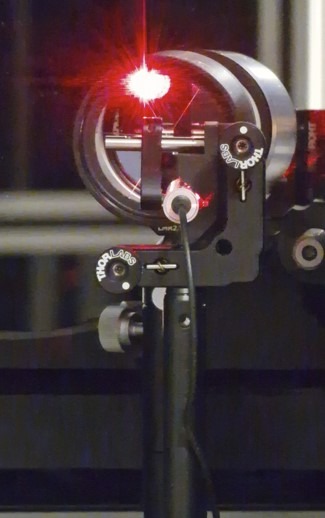
The new method introduces two additional elements: a 637 nm laser pointer and a retroreflector.
A retroreflector is an optical element designed to return incident radiation towards its source with minimal angular deviation. This principle is widely used in optical metrology and ranging applications. One of the most impressive examples is lunar laser ranging, where laser pulses are transmitted from Earth towards retroreflectors placed on the Moon and the returned signal is used to determine the Earth–Moon distance with extremely high precision.
We use the same fundamental principle in our laboratory — just on a much smaller scale.
How do we do it?
The procedure consists of several steps.
First, the rangefinder is fired towards the OAP mirror and its optical axis is adjusted so that the returned rangefinder spot is positioned at the center of the VIS-SWIR camera detector. This establishes the reference position of the rangefinder beam with respect to the camera.
Next, the 637 nm laser pointer is aligned to the same position on the detector. The laser pointer therefore becomes an external visible reference for the established boresight direction.
A retroreflector is then introduced into the beam path in front of the laser pointer. The retroreflector returns the 637 nm beam back towards the OAP mirror and, consequently, towards the camera. Appropriate neutral-density (ND) filters are used to attenuate the returned optical power and protect the camera detector (Unit Under Test – UUT) while maintaining a well-defined laser spot.
The position of the returned laser spot is then evaluated using dedicated image analysis software. By accurately determining the spot centroid relative to the camera reticle, we can quantify the residual angular offset and perform the final adjustment of the boresight camera.
In other words, the procedure provides a clearly defined optical reference chain:
Rangefinder beam → detector center → 637 nm reference laser → retroreflector → camera (UUT) → image analysis*
This approach significantly simplifies the alignment process while providing a quantitative and repeatable method for verifying the final boresight position.
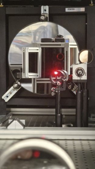
What we are doing in our laboratory is, in principle, the same optical concept used in much larger-scale applications such as lunar laser ranging — NASA technology, but on a micro scale in our lab.
For us, it is another step towards improving the accuracy, repeatability and quality of our optical alignment procedures — ultimately helping us maintain the highest possible standard for our customers.
Let us know how we can help you with your challenges? We are ready to support you and get you what you need.